Continued wingtip lighting
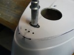
February 11, 2013 – I continued work on the wingtip lighting by drilling screw holes for the plexi for the strobes, then drilled the strobe holes.
I drilled the holes in the plexi to 1″ to fit the strobe itself.
I took the corresponding holes in the fiberglass underneath to 1 1/2″ to fit the body of the strobe. This will allow the strobe to sit higher in the opening. I will attach the strobe to the plexi and the aluminum underneath, instead of also going through the fiberglass.
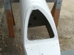
I then cut out the face of the wingtip cutout where the nav lights will be. This will allow for a bit of cooling. Some people have installed heatsinks onside the wingtip. I’m going to wait to see how hot the LED assembly will get before I go through that work. It will save a little bit of weight.
Below is the sequence for these cutouts:
I drilled the nutplate holes, countersunk them, and installed the required nutplates.
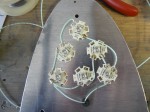
Then I started in on the soldering. I have to do some research, but I had a heck of a time soldering to the contact points on the LEDs, plus I know now some have to be redone because the wires run where the plexi will sit down on top of the LED assemblies.
Here’s my initial wire arrangement:
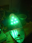
Hooked up the driver and power…and…WooHoo! It worked.
This puppy is BRIGHT!!! Some of the trial and error work is done, no smoke leaked out, so I can clean up the wiring a little bit, learn from my mistakes, and move on.
Time: 5:30


