
April 1, 2015 – I am putting brake pedals on both sides, so the airplane can be fully operated from either seat. By way of explanation for some who aren’t as familiar with the RV setup, the rudder pedals are made of welded tubing and is installed for both seats. The brake pedals are attached to the rudder pedals. The stock setup is to only have brake pedals on the left side for the pilot. This can prevent unwanted brake activation from the passenger. Some builders just have the brake pedals on the left side, others put brake pedals on both sides. So the bulk of the work you see here in the next few posts is for the brake pedals.
I started the pedals by cutting 8 angles 4″ long. These attach to the sides of each brake pedal.
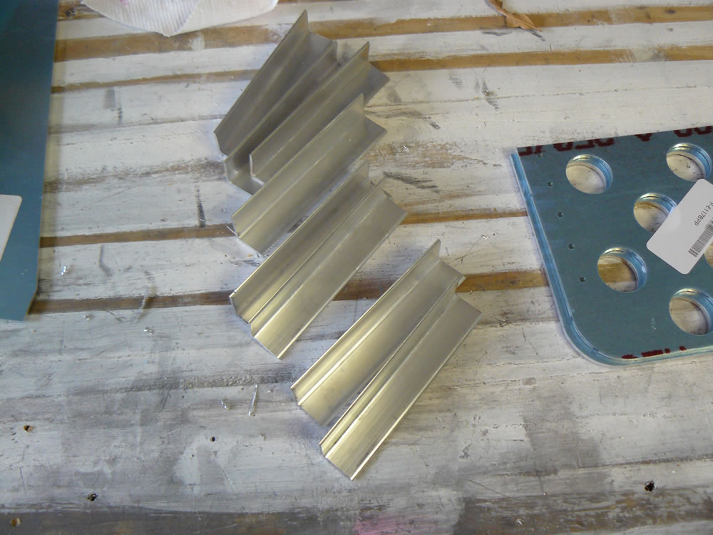

Each pedal also has a bracket for attaching the brake master cylinders. These all get drilled to the pedals. It’s easy to forget that left and right pedals have to be made. They are mirror images of each other.
I also countersunk the pieces as appropriate.


Here’s the pedals clecoed and ready for later assembly (front and rear views).

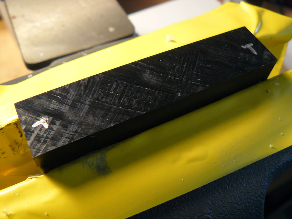
The rudder pedal tubes are supported at the airplane structure by hard plastic wear blocks. These have to be drilled to the airplane. I drilled these blocks like I did the flap blocks. Many people use a drill press to make sure the holes are straight. I do it by hand, and the holes are straight if you are careful.
I marked the hole locations on the top and bottom of the blocks.

Using a #30 drill bit, I drill halfway through the block, then turn the block over and do the same thing. The theory is that the holes will meet in the middle.

I used a reamer to take the holes to final size. The reamer will clean up any minor inaccuracies if the starter holes didn’t perfectly line up.


I also drilled the center support block the same way. I use a silver Sharpie to mark these black plastic blocks.
The side blocks are to be placed no closer than 3″ from the aft face of the firewall. I marked that point on the side angle in the fuselage, then used a long #10 drill to back drill the angle.

You are allowed to drill additional holes to allow for fore and aft adjustment of the pedals. I marked mine 1 1/16″ aft of the original forward-most location, and then an additional 1 1/16″ aft of that. So I have six holes for future pedal fore and aft adjustment.

I started assembly of the pedals out on the table. I have to install the brake master cylinders. Since the pedals are offset from each other, I had to stand back and think about how to locate and position the pedals. More to come on that…
Time: 5:00