F705 Bulkhead
March 19, 2014 – Well, there’s nothing like having work done in the house to chase you out into the garage to do other things. What a shame.
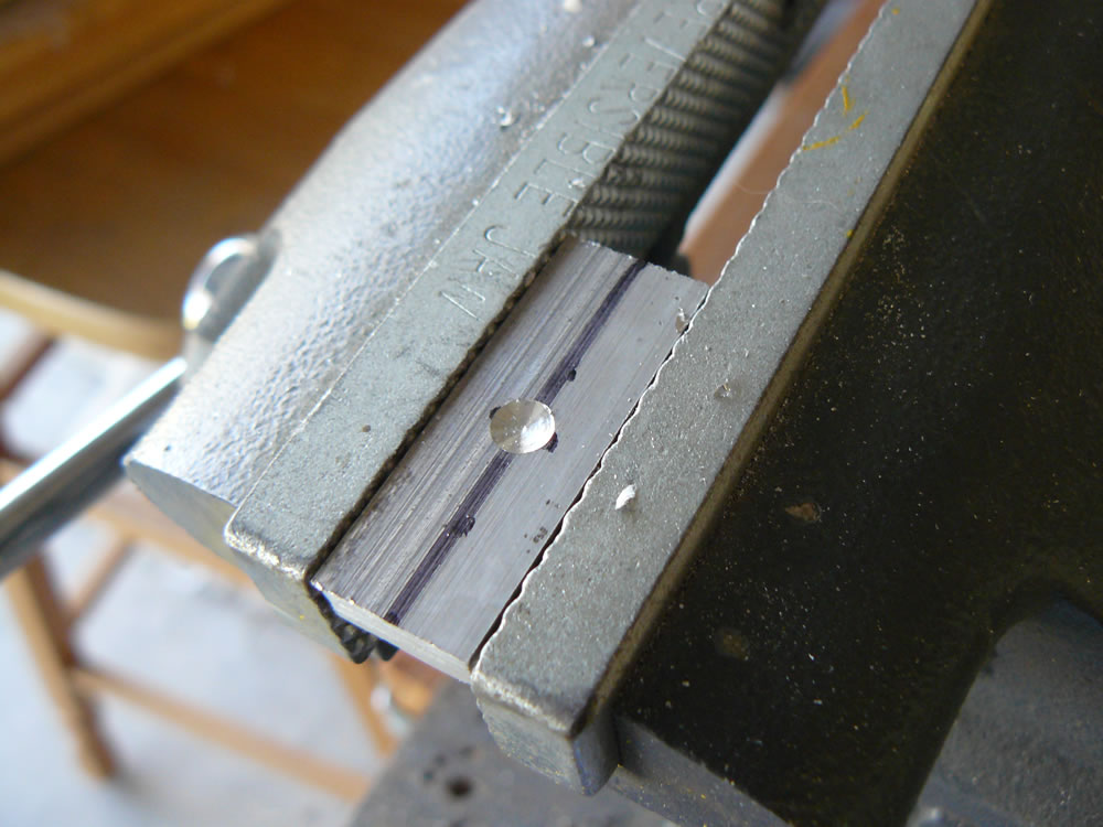
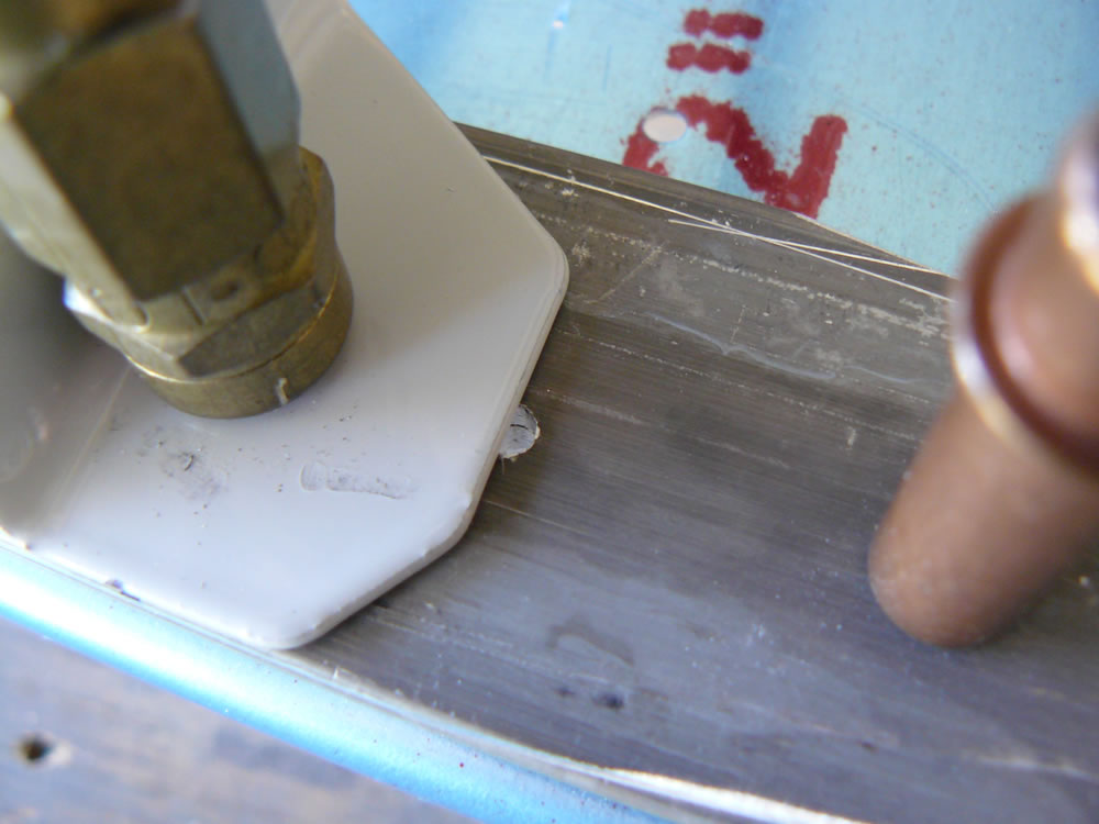
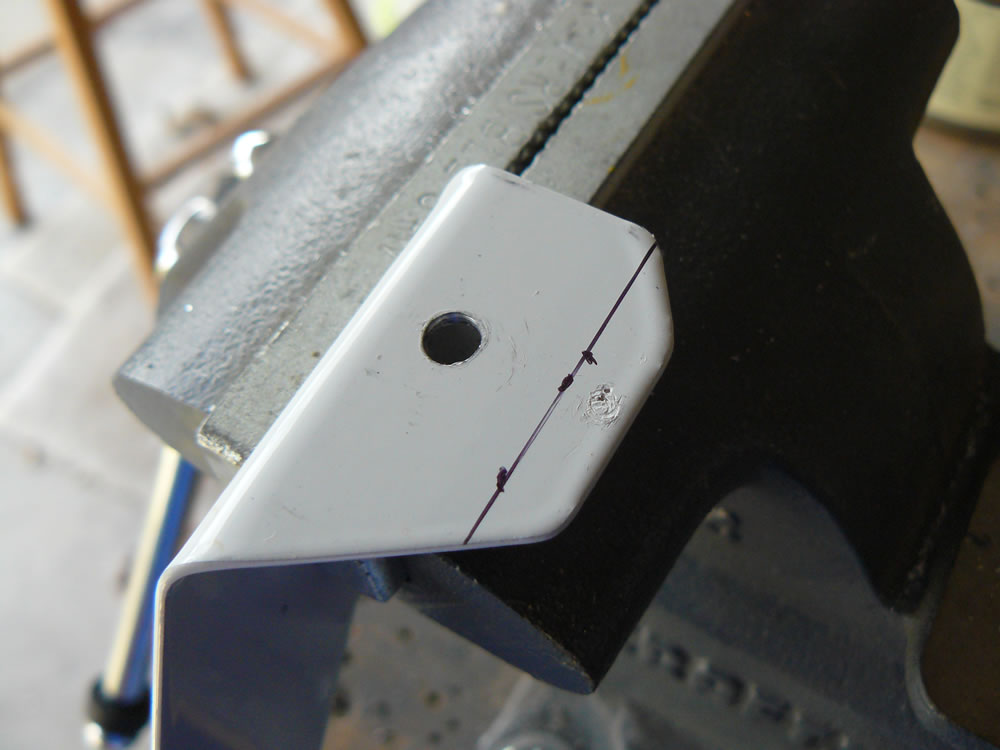
After drilling the strap that goes all the way across the bottom of the bulkhead, I needed to drill the two small spacers. I marked their centerlines and placed them over the hole in the channel and the strap. In the picture below you can see the crosshairs of the centerline marked on the spacer:
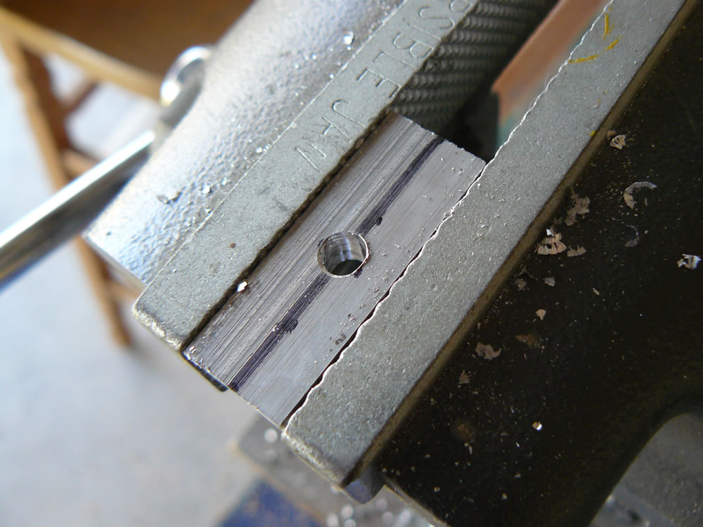
Once the centerline was verified, I moved the spacers to the vise and drilled them:
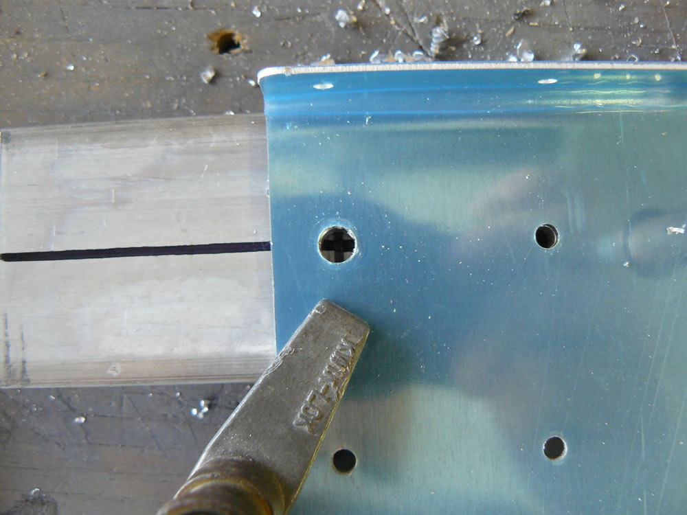
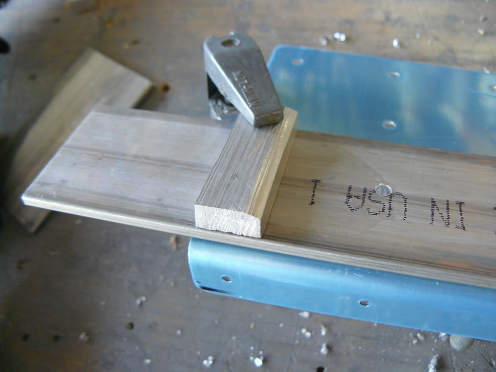
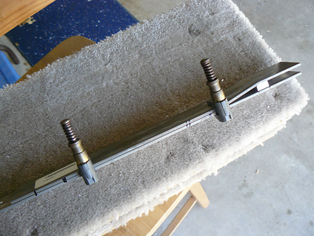
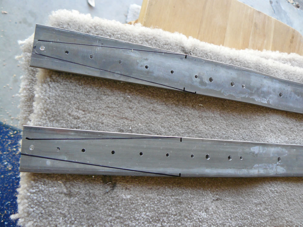
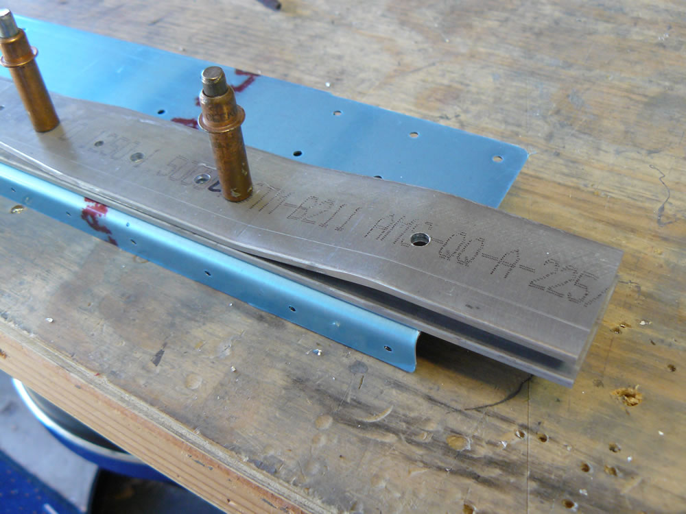
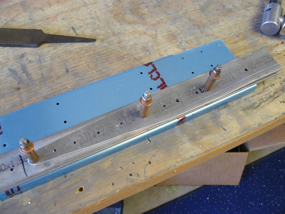
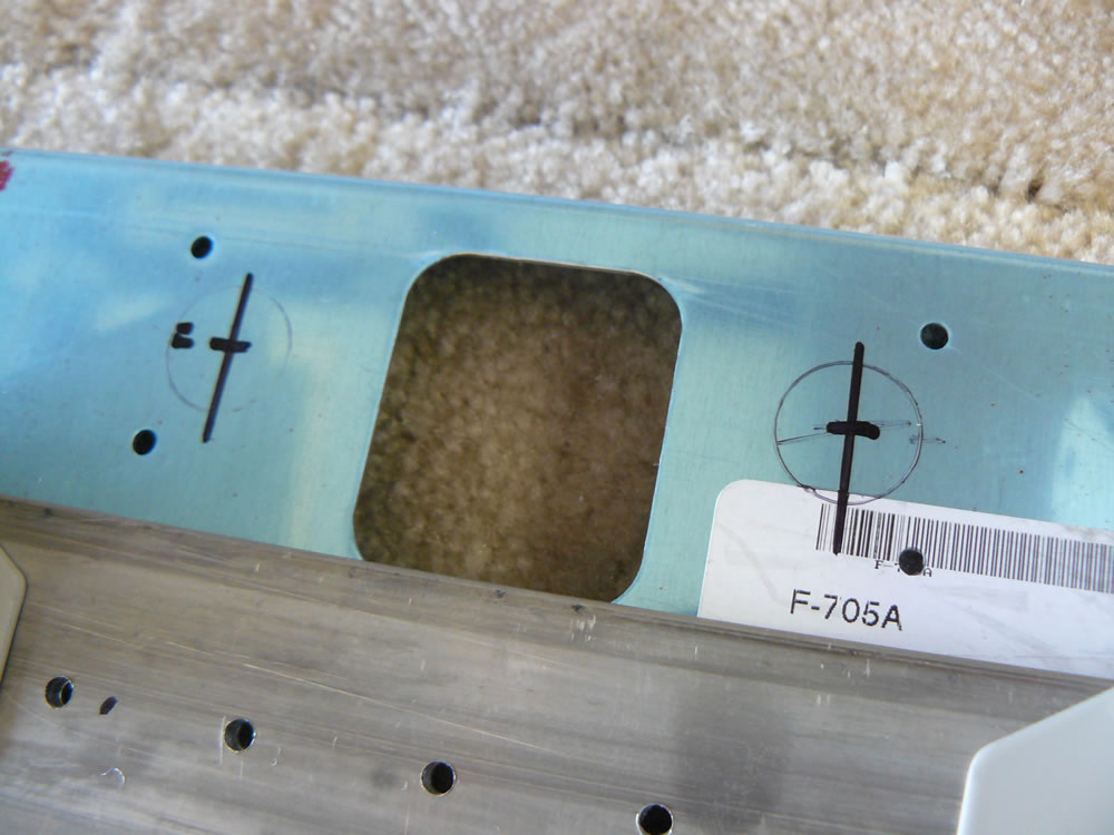
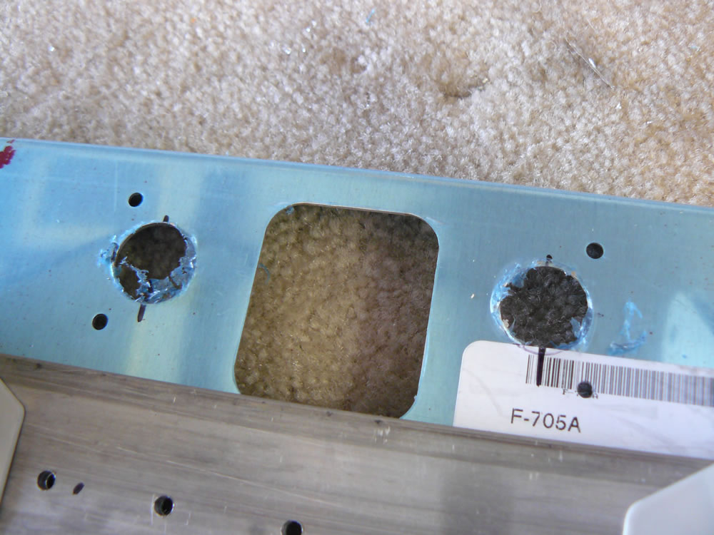
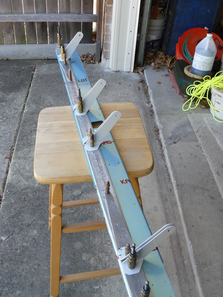
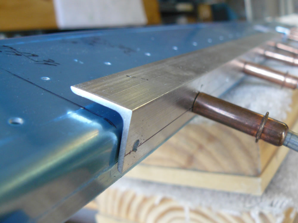
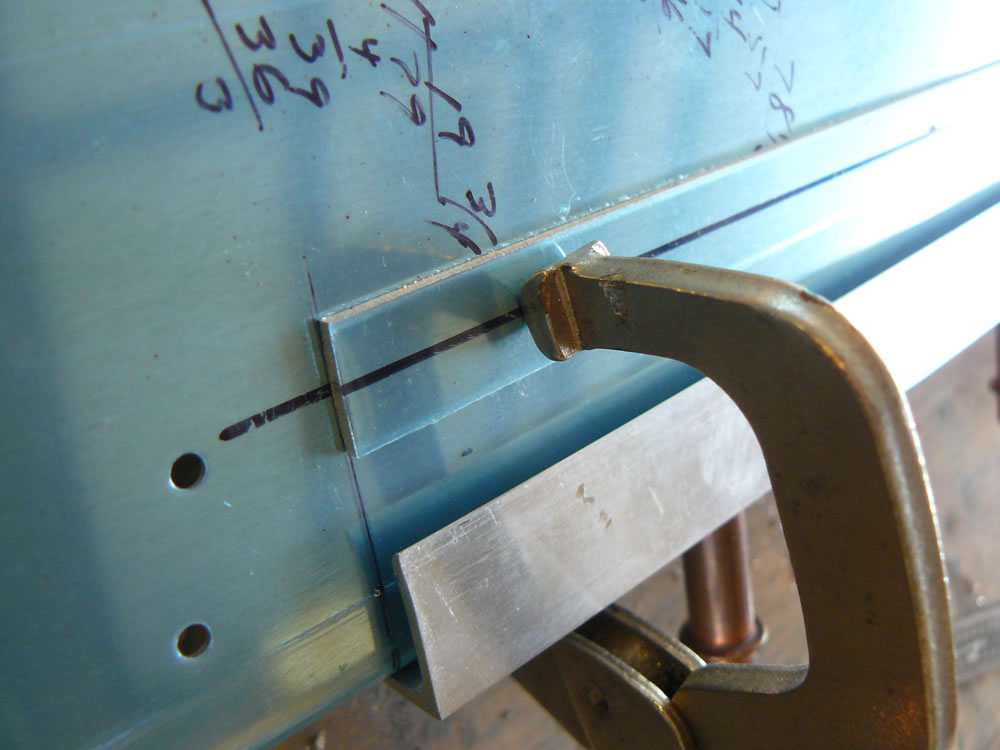
Then it was time to drill the F605C straps. These form the “fork” that will attach the wing aft spars at the fuselage. The plans call for trimming these to length but I waited until they were drilled, so I could ensure good edge distance for the holes. here they are clamped in place, with the previously drilled spacers.
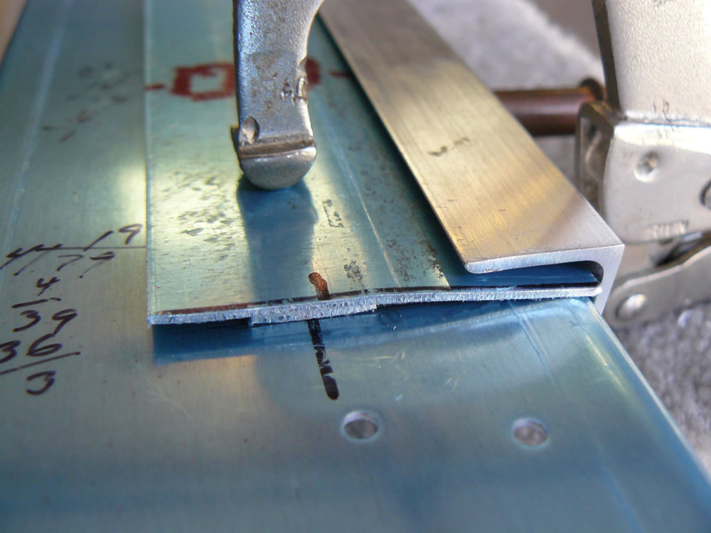
The outboard ends needed only about 1/4″ removed:
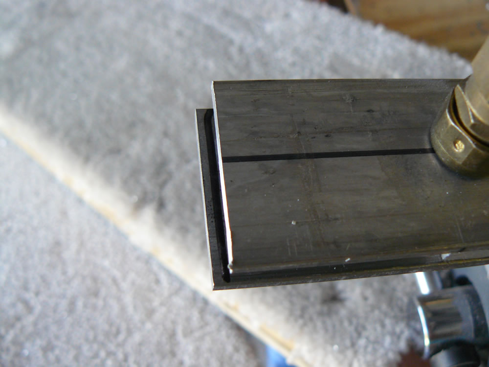
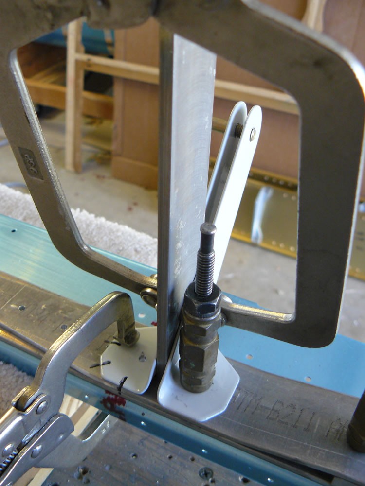
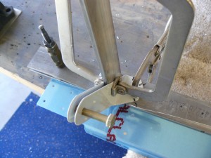
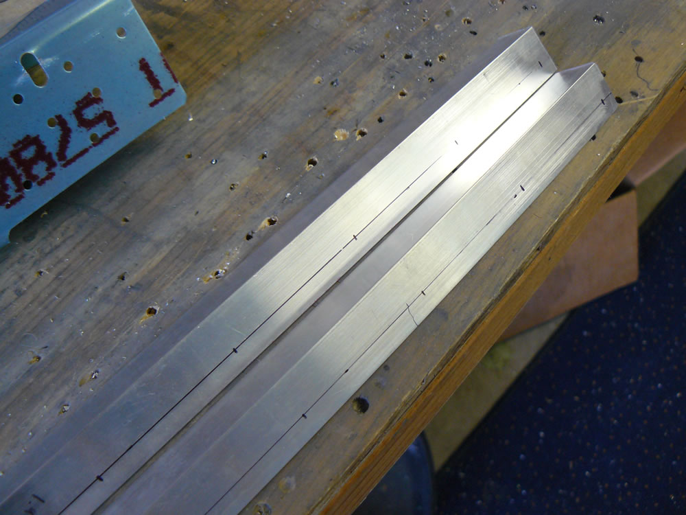
After they were drilled, they needed to be tapered. I took them to work and put them on the bandsaw there.
Before and after trimming:
Then I drilled the seat belt anchors. The plans say to drill the left ones of each pair, then drill the right ones in place. I used the dimensions on the plans as a guideline. I needed to have the anchors flush with the bottom of the strap, so I marked edge distance and drilled the left ones to the strap.
The anchors need to be 3/16″ apart, so I made up a contraption to hold that 3/16″ spacing so I could drill correctly. I used a piece of .187″ bar that came with the kit to give me that spacing, then clamped that in place. I clamped the right anchor in place, and used a bolt to make sure the bolt holes between the two anchors lined up.
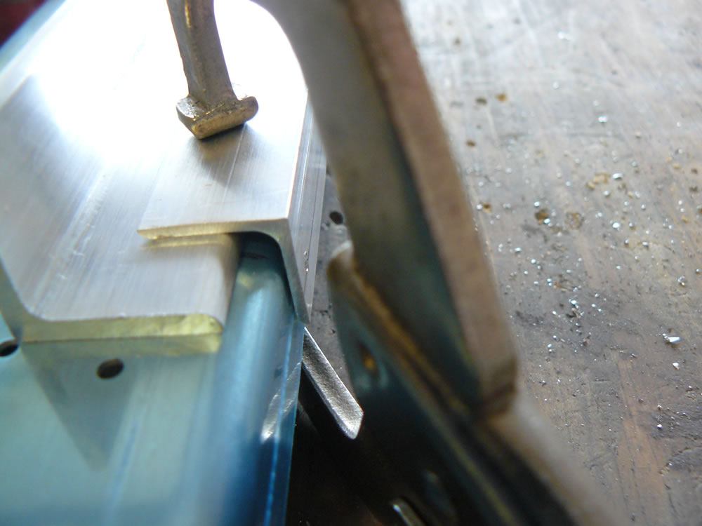
Once they are all in place, you have to trim the outboard sets due to fastener interference. I marked those and cut, then deburred them.
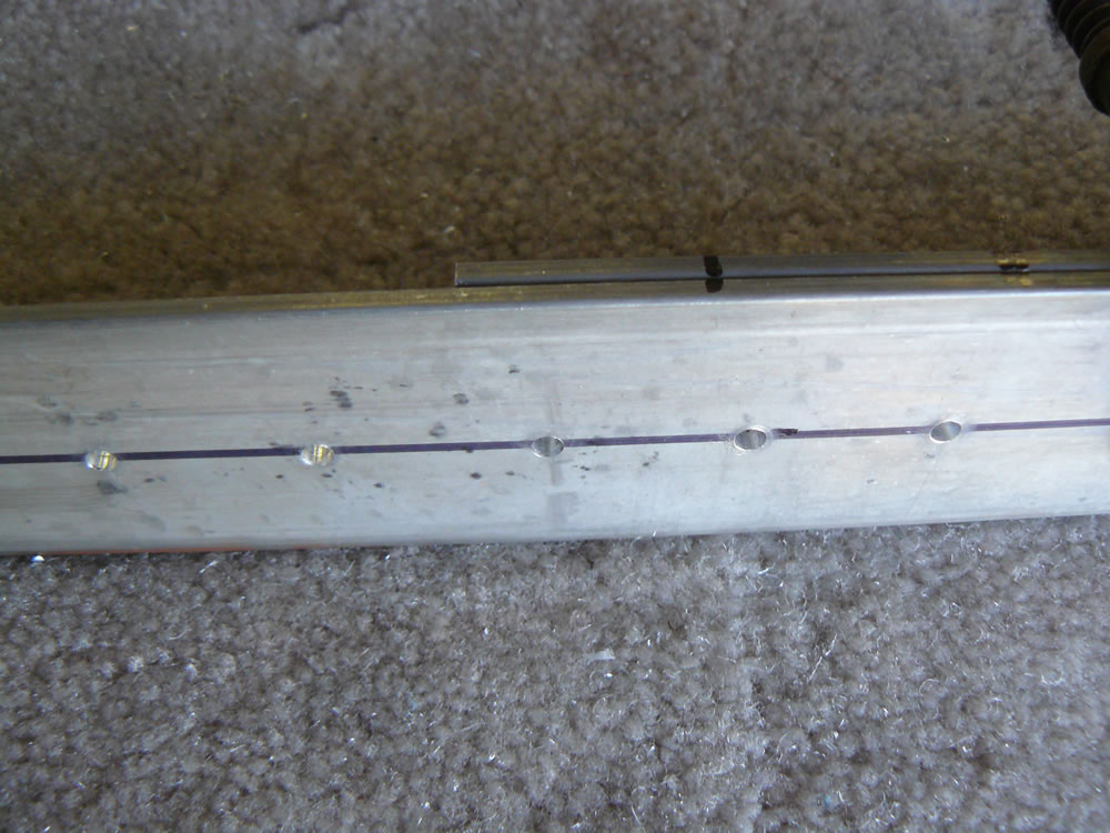
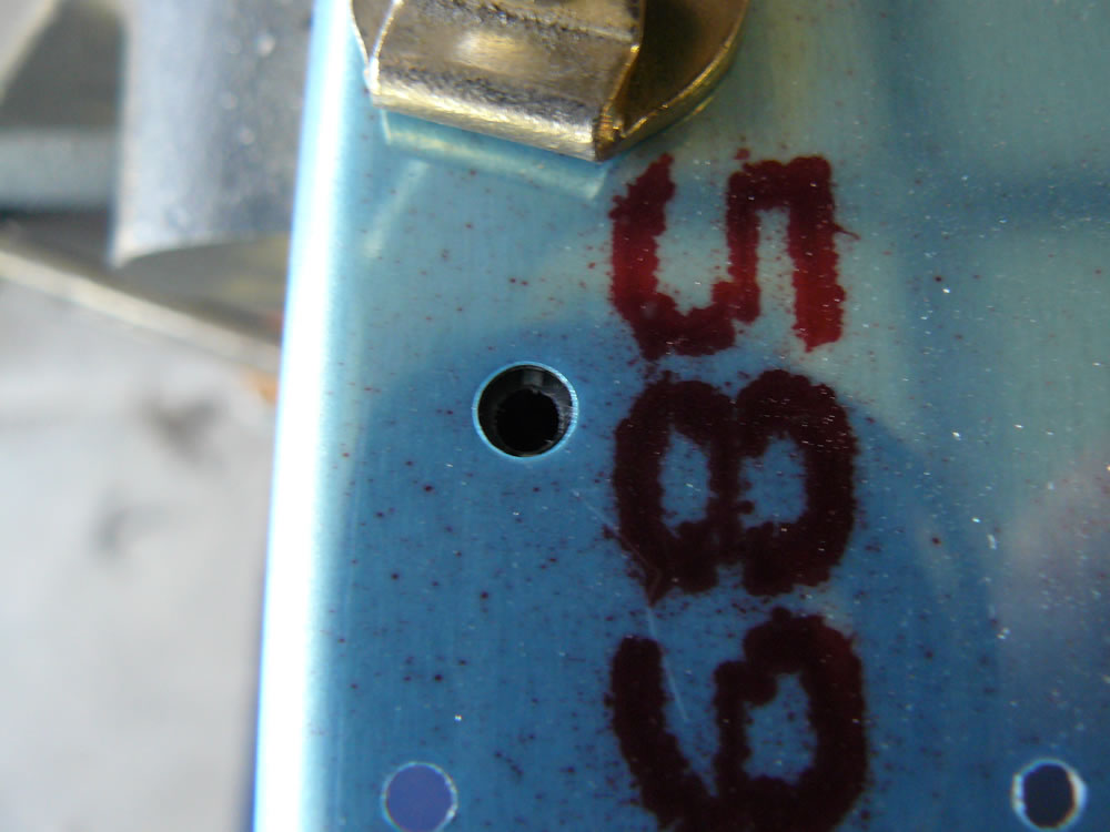
I also had to drill two 5/8″ holes for snap bushings to accommodate wiring. There are other holes in this area, so I made sure edge distance would be good, then drilled the holes.
That takes care of the bottom part of the F705 bulkhead.
The top portion of the bulkhead has structure for seatback adjustment.
I started with the two angles that mount to the back side of the top of the bulkhead. These are 16 1/4″ long, and get 9 fastener holes drilled in them. I’ve never used a rivet spacing fan; never really needed to. It’s just a little math… I marked the centerline for the rivets, then 1/4″ off each end for the end fasteners. Located the halfway point between those (7.85″). That’s the center fastener. Then divide that by 4 to give you the rivet spacing (1.975″). That works out with Van’s suggested spacing on the plans. I piloted those holes in the angles.
The plans call for these angles to be 1/9″ off the top of the channel. I used a piece of angle that was 1/8″ think and clamped it all together. Drill it, remove the spacer, and ta-da!!!
There are two pieces of strap that you have to bend to 4 degrees down the centerline. Kinda wish Van’s provided these pieces, but hey, I’m building an airplane. The least I can do is make some things… I took the pieces to a friend’s hangar and bent them on his brake. 4 degrees isn’t much, so of course I bent them too much, but it can be adjusted.
I located the fastener line on these per the plans, then stacked them with 1/2″ wide shim stock, and drilled them all.
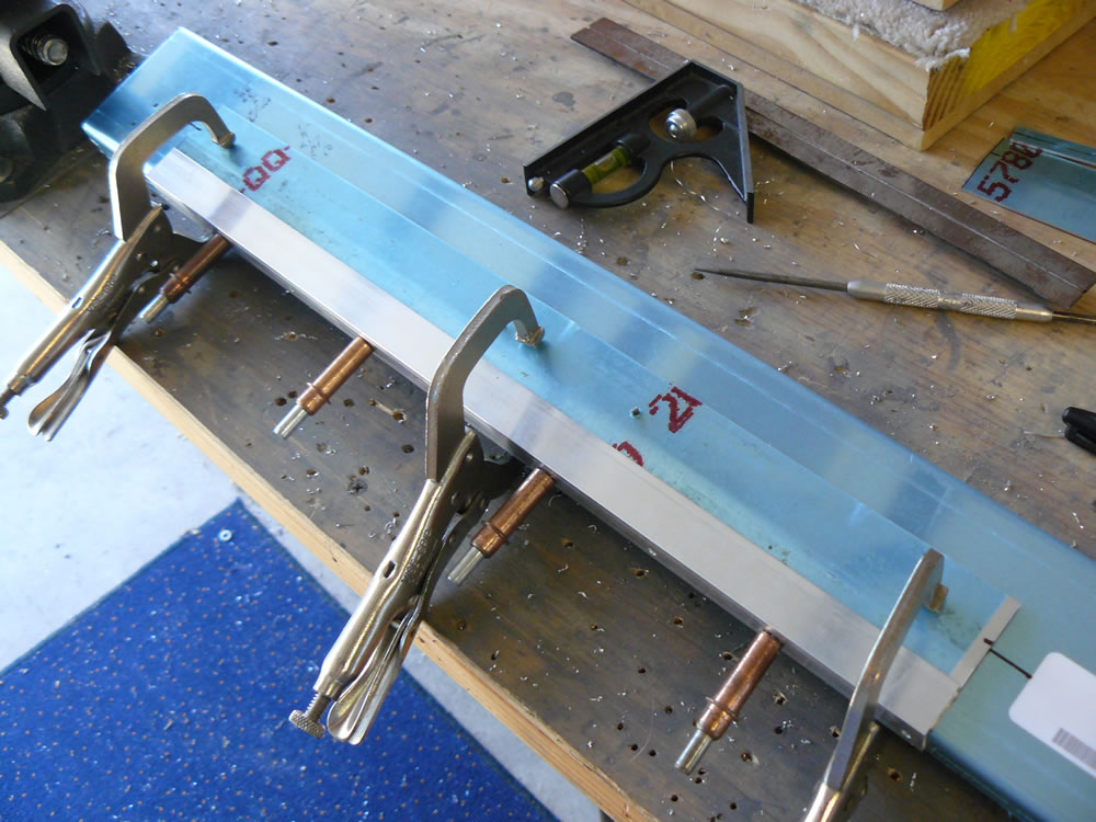
I clecoed the entire bulkhead together. This is very cool.
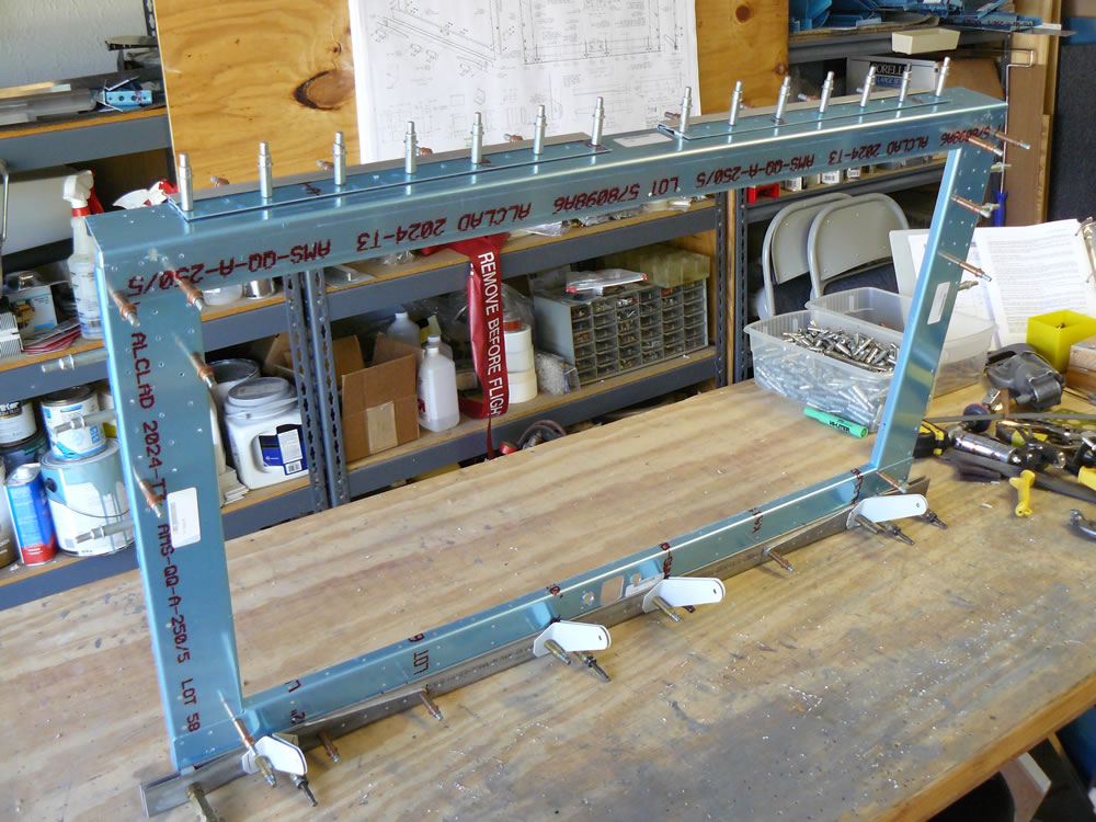
There are doublers that go into the side channels up at the top. I placed them in there and found that the holes were about 1/2 hole off. I finally called the Van’s tech support people. They were and are very helpgul and patient. We determined that even tough there was a small disparity between the holes when I clecoed the side holes, it would come out when I drilled to final size. And that’s pretty much the case. I just kind of freaked out because I’ve never seen holes not match up on these kits.
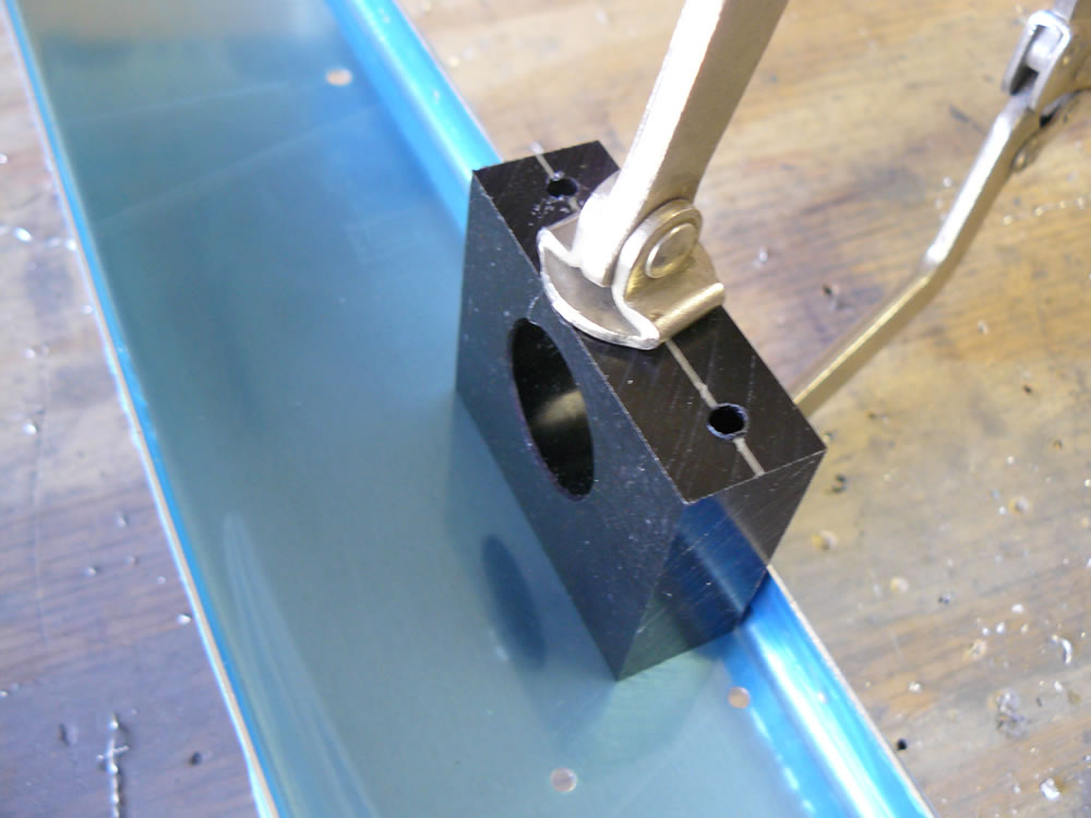
The last thing to do was to drill the flap bearing blocks. These are black plastic blocks. I decided to mark the centerline and the hole locations on both sides of the blocks.
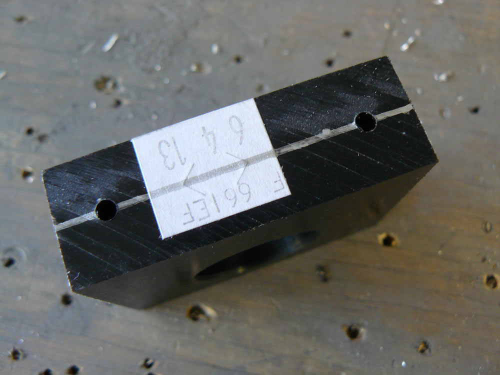
I manually drilled using a #30 bit partway through on each side and hoped the holes would meet up. They did. Then I clamped the blocks in place on the side channels so the holes would line up. You can just see the smaller hole in the block there in the second picture:
I ran a .189″ core drill through there. Perfection.
Time to take everything apart. I removed the blue plastic, and now I have a pile to deburr and paint.
Time: 5:55