Category: Forward Fuselage

Finished fuselage canoe riveting

June 16, 2015 – I finally got my firewall sealant this last weekend, so I did that first.

I put a pretty good bead all around along the rivet holes. I was concerned that I’d use it all before I got all the way around, but I still had some left over when I was done.

061615001 061615002 061615003

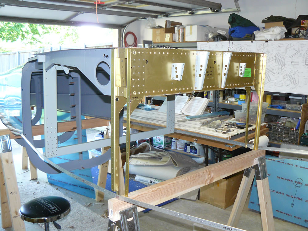
I clecoed the lower skin in place for good.

061615004

My buddy Stan came back over and we shot what was left on the fuselage.

061615006 061615005

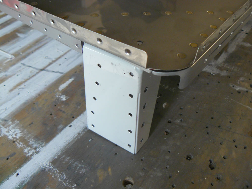
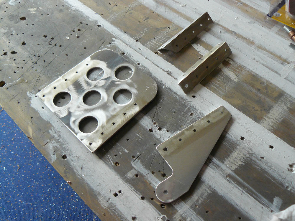
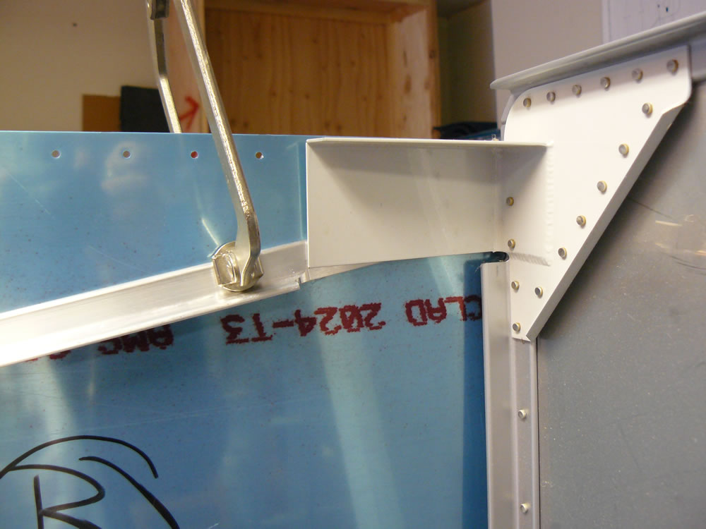
I had to remove the attach brackets for the sticks so I could get to those rivets cleanly, so afterwards I put those back on.

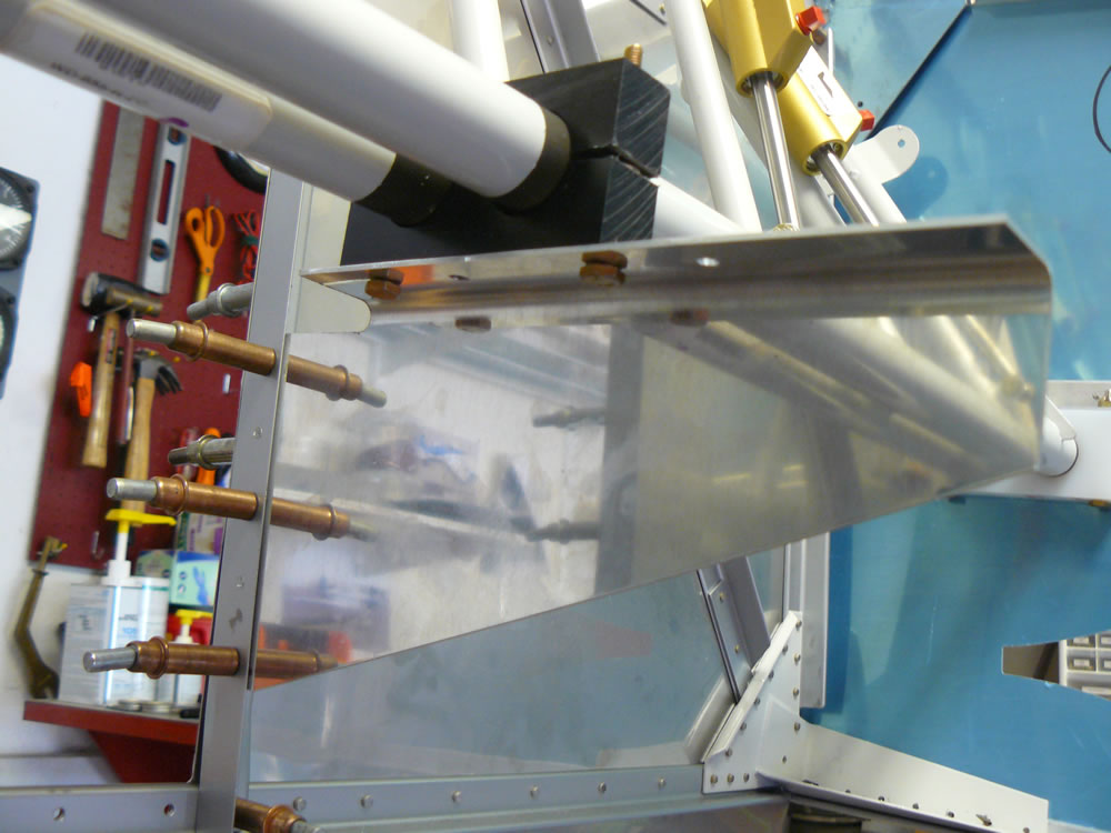
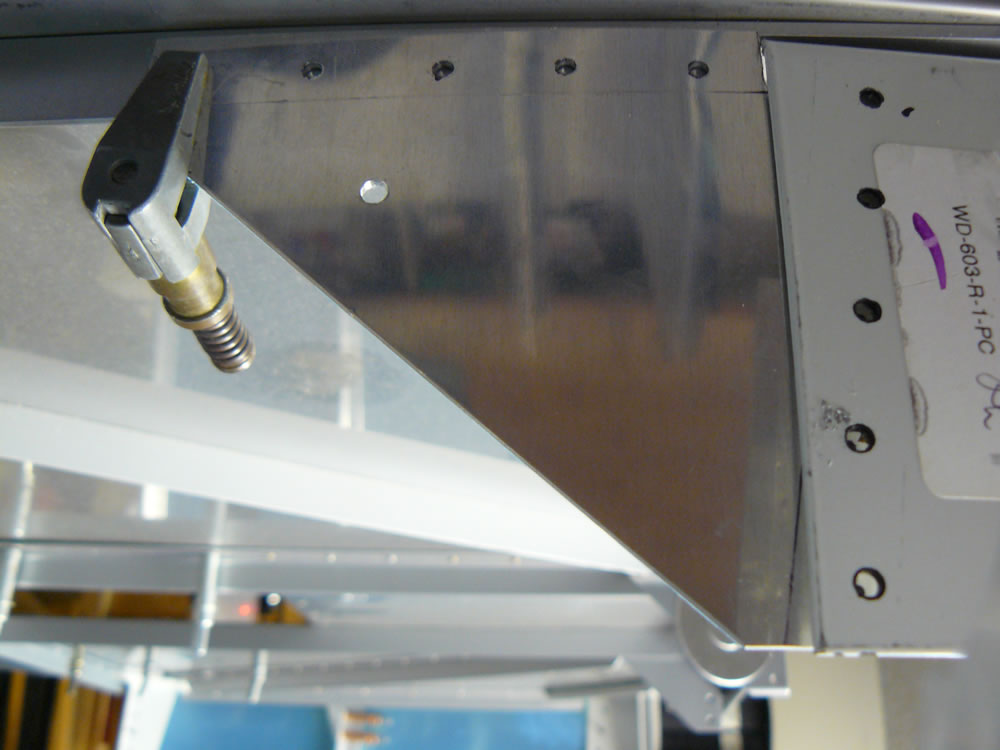
I put the F728 angle in place, because I didn’t want to shoot rivets in the belly with the canoe right side up if I didn’t have to.

061615007

Pretty cool view from under here…:

061615008

Time: 5:15

Fuselage tasks

June 10, 2015 – Since I am waiting on my firewall sealant to finish the forward lower skin, I decided to look at some things that I could get done. Turns out I’m glad I did some of this now because it would have been a pain with the fuselage rolled upright.

I did install the bolts for the lower firewall corners where they tie to the longerons.

061015002

I decided to do the gussets that go in the lower corners between the F704 center wing spar and the F7101 gear attach webs, and the attach angles for the F782 cover plates.

I bolted the F7114 gussets in place and drilled them. The holes through the skins get bolts, so I ultimately reamed those holes to .189″

061015004 061015003

I cut the F782D angles out of the material provided and shaped them. In order to find their location against the F7101 gear attach webs, I used a long straight level and laid it against the other brackets inboard of this one, and marked the location of the front face.

061015007

The cover plates had to be modified. Because I used 1″ flange angle for the center floor stiffeners, the slot at that point had to be extended.

061015005 061015006

Back to the angles. These angles get attached to the gear attach web, which is just inboard of the outer skin. You do not want to drill all the way through, so I put a drill stop on the drill I used, then drilled the holes.

061015008 061015009

I alodined and painted the angles and gussets.

061015011 061015001

I also installed the aft baggage side covers that are fixed panels.

061115001

Time: 6:00

Continued riveting fuselage

June 2, 2015 – After my little setback attaching the baggage compartment ribs, my friend Stan came back over and we finished riveting the skins.

060215010 060215011

Then I slipped the firewall into place. I had put off buying the firewall sealant thinking I could get it locally (3M Fire Block 2000). I couldn’t find it anywhere, so I ended up ordering a tube of Flamemaster CS1900. It’ll be at least a week before I get it.

Anyway, I loosely clecoed the firewall into place, knowing I’d have to have access to the flanges to apply the sealant.

I installed the rivets attaching the F719 angle clips to the firewall. I pulled the skin back enough to get my squeezer in there.

060215012 060215013

After the firewall was in place I installed the center floor stiffeners.

060215014 060215015 060215001

Time: 3:30

Continued fuselage assembly, Part 2

May 27, 2015 – Just been plugging along riveting the fuselage. I’ve done quite a bit by myself.

I installed the bulkheads and ribs for the baggage compartment…

052715001 052715005 052715006

…and I installed the armrests:

052715007 052715002

I installed the rivets that attach the bulheads to the longerons:

052715004

I started installing the rivets that attach the F615 seat ribs to the skin. On this side I did as far as I can reach by hand by myself. I’ll get some help to finish these, among other areas.

052715003

Here’s an overall view:

052715008

Time: 3:30

Continued fuselage assembly

May 21, 2015 – I continued assembly of the fuselage with some small items and then started riveting.

I installed some nutplates in some of the bulkheads.

052015003

I also worked on the fuel tank attach angle assembly inside the fuselage. The lowest fastener, a bolt through the skin and the longeron, needs to be reamed up and then machine countersunk through the skin and longeron to accept a screw.

052015004 052015005

052015006

I clecoed it all together and it got riveted a little later on.

052015007

I riveted the gear attach webs and their associated structure.

052015002

I also did the rivets that could be done on the longeron where upper skins are not involved.

My friend Stan came over and we started the riveting that took two guys to do.

052015008

We got a bunch done on the right side, and worked our way back to the conical bend.

Behind the aft spar I had to remove the bolt for the fork spacer so I had access to the rivets in that corner.

052015009

Here’s a couple shots of the work that we got done on the right side:

052015001 052015010 052015011

Time: 11:00

Started fuselage assembly

May 13, 2015 – I started some of the final assembly of the fuselage.

I have never been able to find out when the F728 bellcrank channel should be riveted together. This attaches to the aft fuselage forward bulkhead (F706). So I riveted it together.

051315014

I riveted the F684 gussets to the firewall, the firewall clips to the F719 stiffeners, and the F7101 gear attach webs to the F902 bulkheads. These are just some sub-assemblies that get put together before being put into the fuselage.

051315001 051315006 051315007

I also pre-riveted the F704H doublers to the side skins. These rivets would be impossible to access after the skins are in place. I tried to make sure I riveted the ones that are called for, but after clecoing the skins in place I see one open hole that probably needs to be done. It won’t be a big deal to do right now. Here’s the outside and inside views of that doubler:

051315004 051315005

I rolled the aft fuselage back right side up and slid the longerons in place. My buddy Carlos stopped in on his way home from work and we put the center section in place, hopefully for good.

051315002 051315003

I had to pull off the forward half of the center wing spar in order to install bolts that, if I was building a -7A (nosewheel) aircraft, would have held part of the main gear attach brackets. Since I’m building a taildragger, these holes essentially just get filled. There are 6 bolts on each side, left and right.

051315008 051315009 051315010

I reinstalled that portion of the spar. Here’s a shot that’s kinda cool, looking through the spar from the side:

051315011

Then I clecoed the left and right side skins in place.

051315012 051315013

Time: 4:00

Fuselage deburring and countersinking

May 4, 2015 – I got a lot done over the last couple of days. We have some weather on its way, plus we are going to my son’s graduation..  (Boomer Sooner!).. so I wanted to get some things painted so the paint can cure a little before starting to install things.

I deburred and countersunk the remaining holes in the tailcone. These are for the forward bulkhead and for the longerons.

050415003 050415004

I took the longerons out onto the driveway, and cleaned, countersunk and painted them. 360 holes got countersunk. I decided to not countersink the holes in the longerons for the canopy rails. Since the rails are .040″ they themselves can be countersunk. I had to clamp the longerons to the sawhorses to get them to stay upright so I could access the holes for countersinking.

050415006 050415001 050415002

I finished the day by alodining and priming all the remaining fuselage parts.

050415005

I still have some things to do, but things are getting a lot closer to fuselage assembly.

Time: 5:48

Fuselage parts prep

April 29, 2015 – Spent just a little time today cleaning the smaller parts, angles and bulkheads and getting them ready for paint.

Then I cleaned and dimpled the three skins; the side skins and the lower forward skin.

042915002

I also dimpled and countersunk the flanges on the firewall, then I deburred all the holes in the engine mount brackets.

042915003 042915004 042915005

I dimpled and deburred the outboard seat ribs and the angle brackets in the center fuselage.

042915006 042915007

While I was doing some of the dimpling somewhere along the line my vise grip dimpler broke. So I called Avery and ordered a new one…

042915008

A friend from work came over and helped me separate the center section from the aft fuselage. We set the center section on the floor, then we rolled the aft fuselage back right side up and pulled out the longerons.

042915009 042915010 042915011

I deburred and dimpled the skin fastener holes on the forward and aft ends of the center section skin. I’m priming the skin that gets overlapped.

042915012 042915013 042915001

I removed the forward bulkhead from the aft fuselage to give me access to the fastener holes there.

042915014 042915015

Time: 9:20

Fuselage to-do list

April 22, 2015 – I had to take care of several things before taking the forward half of the fuselage back apart.

I finished back-drilling through the side skins. This included the F715 seat ribs and various attach holes where bulkheads are attached at top and bottom.

042215006 042215009 042215008

I also had to drill several larger holes for fuel lines coming in, and fuel vent and brake lines.

042215013 042215012 042215011 042215010

I also marked where skin panel lines were, so I could paint the faying surfaces of those skins at those locations.

042215014

I also had an issue with where the rudder pedal blocks are attached on the right side.

I got my left/right, up/down confused on the right block, and messed up a couple of holes in the F719 angle.

042215032

I decided to make a strap that will be on the lower side of the angle and will provide a good bearing surface and good holes for the bolts. I drilled that and added four rivet locations to secure the strap.

042215031

On another happy note, I got my brake pedals back from powdercoat. They came out pretty nice. You can’t really tell, but they have a rough texture.

042215041

Time: 1:45

Drilled floor stiffeners

April 22, 2015 – Well to start with, the dates on the next few posts are skewed, because I haven’t had internet access at home for a week. It’s a good thing I have this project because I would have gone totally nuts…

I kept  good track of my time, but I’m writing all these posts on the same day…

So I drilled the floor stiffeners. The outboard ones were a non-event. Not really even any pictures.

I then clamped the inboard stiffeners in place. I quickly realized I might have a problem because I had drawn a centerline on top of the stiffeners, and couldn’t get that line to appear through the holes in the skin. Yes, I’m sure they were in the correct location, and left and right were correct.

I decided to go for it and drill them to see where I stood. Here they are clamped in place, and then drilled:

042215001 042215002 042215003

Here they are from underneath:

042215004 042215005

I had minimal edge distance for the holes to the edge of the angles. Strictly speaking, it was legal, but I didn’t like it. Here’s an angle out on the table:

042215015

I decided to replace the angles with 1″ flanges instead of the 3/4″ angles provided. I found the same angles at Aircraft Spruce.

I knew when I was ordering them that I’d have to decide how to fit them, because the originals are joggled to fit over the firewall angle and the F704 bulkhead flange. I decided to attempt to joggle them.

I cut them to length, and had about an 8″ piece of scrap off each one. I tested my joggles on those scraps. Here’s how I did it:

A quick lesson in joggles:

Since the angle fits over a flange on the firewall that’s .125″ (1/8″) high, I used 1/8″ scrap to do the bends. I found two pieces of scrap, and rounded the edges that would contact the angles, in order to prevent scarring the metal.

042215016 042215017

I taped the pieces on opposite sides of the angle flange to be bent.

042215019 042215020

Then  I placed the whole thing in the vise. After a couple of tests where I really tightened the vise hard, I realized I didn’t have to try that hard; just making it snug did the trick.

042215021

And here’s the joggle. It’s at least as good as they come from Van’s:

042215022 042215023 042215024

Back to our story:

Now I could get back on track. I clamped the angles in place. You have to notch the forward ends to allow clearance around one of the angles on the firewall.

042215025

I drilled the angles through the skin, then drilled through the angles at the forward and aft ends.

042215026 042215027 042215028

Now, I haven’t figured out what the original problem was with the fit, but I think the heavy angles on the firewall are off by a hair, because when I unclamped the stiffeners, they sprung out a little bit.

042215030

I decided just to shim the stiffeners at these angles.

042215029

Time: 6:20

Made rudder pedal center support

April 8, 2015 – Yesterday I took the brake pedals to get powder coated. Then I made the center support for the rudder pedals.

I trimmed the bracket to clear the firewall recess, and marked out the holes to attach the bracket to the firewall.

040815002

With the rudder pedals in place, I put the bracket where it belongs, and drilled. Since the rudder pedals are ground-adjustable fore and aft, I had to drill multiple sets of holes. I only drilled two sets of holes, where I had drilled three sets on the outboard ends. I decided that the aft-most setting would most likely never be used.

Here’s the bracket seen from inside and outside:

040815004 040815003

Here’s the drilled bracket:

040815005

Then I shortened the bracket, removing the unused portion, and I cut a lightening hole.

040815006

I test fit everything one more time before taking it all out to start on the floor stiffeners.

040815001

Time: 2:25

Continued rudder pedals

April 3, 2015 – I needed to figure out where to position the brake pedals so they’d be out of the way during normal rudder use. I decided to place them a bit forward of center.

I clamped the rudder pedal “hangars” together so they were in line all the way across.

040315002

I then clamped angles to the brake pedals so they were in the same parallel position. The angle rested against the back side of the right rudder pedal, since the pedals are offset from each other. This gave a forward angle of a few degrees from vertical.

040315001

With both pedals tied together in the same relative position, I could drill the holes to attach the brake master cylinders. I used the trick so many others have done: placing a drill bit through the mount hole of the master cylinders and marking a line on the tab of the pedals.

040315007

I marked the center point on that line and drilled using a #30 bit. Then I placed a reamer through the master cylinder mount holes and took the holes up to size.

040315003

I placed the rudder pedals into place in the fuselage to check the fit. Got a little mixed up between left and right, and the side blocks are drilled slightly at an angle to allow for fuselage taper. You can’t really see it but the blocks didn’t fit well. I figured out their correct orientation and all is well.

040315004

I want to powder coat the pedals for wear resistance. I assembled the four pedals, and am waiting to get them  out for powder coating.

040315005 040315006

Time: 3:20

Started rudder and brake pedals

April 1, 2015 – I am putting brake pedals on both sides, so the airplane can be fully operated from either seat. By way of explanation for some who aren’t as familiar with the RV setup, the rudder pedals are made of welded tubing and is installed for both seats. The brake pedals are attached to the rudder pedals. The stock setup is to only have brake pedals on the left side for the pilot. This can prevent unwanted brake activation from the passenger. Some builders just have the brake pedals on the left side, others put brake pedals on both sides. So the bulk of the work you see here in the next few posts is for the brake pedals.

I started the pedals by cutting 8 angles 4″ long. These attach to the sides of each brake pedal.

040115012 040115013

Each pedal also has a bracket for attaching the brake master cylinders. These all get drilled to the pedals. It’s easy to forget that left and right pedals have to be made. They are mirror images of each other.

I also countersunk the pieces as appropriate.

040115015 040115016

Here’s the pedals clecoed and ready for later assembly (front and rear views).

040115014

The rudder pedal tubes are supported at the airplane structure by hard plastic wear blocks. These have to be drilled to the airplane. I drilled these blocks like I did the flap blocks. Many people use a drill press to make sure the holes are straight. I do it by hand, and the holes are straight if you are careful.

I marked the hole locations on the top and bottom of the blocks.

040115017

Using a #30 drill bit, I drill halfway through the block, then turn the block over and do the same thing. The theory is that the holes will meet in the middle.

040115018

I used a reamer to take the holes to final size. The reamer will clean up any minor inaccuracies if the starter holes didn’t perfectly line up.

040115019 040115020 040115021

I also drilled the center support block the same way. I use a silver Sharpie to mark these black plastic blocks.

040115022

The side blocks are to be placed no closer than 3″ from the aft face of the firewall. I marked that point on the side angle in the fuselage, then used a long #10 drill to back drill the angle.

040115023

You are allowed to drill additional holes to allow for fore and aft adjustment of the pedals. I marked mine 1 1/16″ aft of the original forward-most location, and then an additional 1 1/16″ aft of that. So I have six holes for future pedal fore and aft adjustment.

040115024

I started assembly of the pedals out on the table. I have to install the brake master cylinders. Since the pedals are offset from each other, I had to stand back and think about how to locate and position the pedals. More to come on that…

Time: 5:00

Finished tank attach brackets

April 1, 2015 – Well, I made the shims for the brackets correctly…

I roughly shaped the angles to the dimensions on the drawings. I found them too big, so instead of going exactly with the drawings, I trimmed each one to fit to the airplane.

040115003 040115004

I drilled the angles through the skin, then used a reamer to enlarge the lower (which is really the upper) hole to .189″, then clecoed that.

040115005

The other hole is a new hole, meaning it does not exist in the skin, so it has to be located and drilled. I drew a line connecting the rivet holes above and below it, so I had a reference centerline to place the bracket hole. I used a drill bushing to drill a smaller hole through the bracket.

040115006 040115007

I made sure the hole was centered, then took the hole up to size with a reamer.

040115008 040115009

…and here’s the bracket, inside and out…

040115010 040115011

Repeated the process for the other side.

Time: 2:20

Continued lower longerons and F684 gussets

March 24, 2015 – I’ve done quite a bit in the last few days and had to get this log caught up.

I put the left side F684 gusset in place along with the lower longeron.

032415004

Backtracking just a little bit, I needed to figure out where to drill the four bolt holes that go through the longerons and the lower engine mount brackets on the firewall. I’ve read many times that the location called for in the drawings will not give enough edge distance for the bolts going through the mount brackets.

I used a scrap piece of the longeron angle, and drew a line where the plans called for it: 1/2″ from the outer edge of the flange. I transferred that line to the mount bracket. Yup, I agree, the edge distance is not good. So I drew a line 1/2″ from the apex of the angle on the flange and transferred that line to the mount brackets. I can live with this edge distance.

So here’s the sequence. The red line is the dimension called for in the plans; the black line is where I placed the line:

032415005

I drilled #30 (1/8″) holes in the scrap angle on the black line:

032415006

I put the angle in place and poked a Sharpie through the holes to get the hole locations. I like it.

032415007 032415008

I drilled the holes with a #30 through the longeron:

032415009

Then I clamped the longeron in place and drilled through the mount bracket:

032415010 032415011 032415012

Here’s the final result from underneath:

032415013

I took the holes up to .189″ using a reamer.

The next job was to drill the F684 gussets.

I pulled the side skins back to drill the holes through the firewall angle. Made sure the gussets were well-clamped and in place, then drilled using an angle drill.

032415014

I then drilled the holes through the auxiliary longeron and the engine mount bracket. The aft hole is a little close, but that seems to be part of the design… Here’s what the gussets look like in place:

032415015 032415016 032415017

I made sure the F902 side bulkheads were fitted well to the lower longerons, and I fitted the F7101 gear attach webs. These webs nest nicely in side the skin between the lower and auxiliary longerons, and the F704 and F7101 bulkheads. I drilled the F902 bulkheads to the skin, then drilled the holes between the web and the F902s.

032415018

I went ahead and drilled the rest of the holes for the lower longerons through the side skins. The plans and instructions are silent on when to do this. I’ve read that some people wait until clecoing the lower skin in place, but this doesn’t make a lot of sense to me. The holes will line up with the side skins.

032415001 032415002  032415019

The next step is to fabricate parts for the tank attach bracket, where the fuel tanks will attach to the fuselage. I misread the plans and made two shims when there should be four, then I mis-identified them. So I have to make new ones, and I’ve learned some tricks about making and drilling these anyway, so it’s OK. So in the interest of full disclosure, here’s my mislabeled shims:

032415003

Time: 4:10

Started F717 Longerons

March 17, 2015 – I’ve been working on getting the F717 longerons in place for drilling. These are very thick angles. I started out by cutting them to length, then creating a cutout on one end. I drilled a hole for the radius of the cutout, then took them to work to cut on a bandsaw.

031715002 031715005

Brought them back home, and used a rotary file, then sanded them down to shape. I just need to do a little final polish after they are drilled.

031715001

I had to put a little twist on the forward end so they would fit in the engine mount bracket on the firewall. Today I’ve been working on the right side; I’ll go the distance with that one, then use lessons learned from it to do the left side.

Along with the longerons, there are gussets that help tie the longerons to the firewall.

These gussets get trimmed and then bent to fit the area. I located some fastener holes, then tied the two gussets together (left and right) to try to make them mirror images of each other.

031715003 031715004

I took them out to a friend’s hangar where a brake lives, and bent the edges as required. I tried to fit the right one in place, using a 1/8″ spacer to keep it 1/8″ aft of the firewall, as mentioned in the manual.

031715007

It will be a challenge to get good edge distance on a couple of the fastener holes, but it works if you just take your time; a lot of fitting, moving, marking, and crouching under the firewall… Here’s the right gusset more or less in place:

031715006 031715008

…and here’s the right side view of the longeron and the gusset as it sits at the moment:

031715009

Time: 3:05

Drilled fwd fuselage angles

March 11, 2015 – I continued with the work in the forward part of the fuselage.

I drilled the longerons where they attach to the upper engine mount weldments. Pretty straightforward; the edge distance might be a little tight, but the mounts were firmly clamped in position with the longerons.

031115001 031115002

I started on the F713 auxiliary longerons by marking the centerline on the outboard face so they could be lined up with the existing holes.

031115003

The aft end of the angles are to be trimmed to fit flush against the flange of the F704 bulkhead. Here’s a before and after:

031115005 031115007

The forward end is clamped in place:

031115004

Here’s the right longeron drilled in place:

031115006

The F719 stiffeners get done next. These have a joggle on the aft end that is pretty rough. I straightened it out as well as I could, then fit it in place. I had to trim the forward and aft edges to an angle so it would all fit properly. The joggle fits over the flange of the F704 bulkhead.

I also had to make the attach angles that secure these stiffeners on the forward end. Once the stiffeners got drilled to the skin, the angles get drilled in place. I had drilled the two holes in the angles where they attach to the stiffeners; I did not drill the hole to attach the angles to the firewall until they were in place.

031115009 031115010

Here’s the product of today’s work (on both sides, of course):

031115008

Time: 4:10